Need help With my circuit. If you have a simulator program, definantly

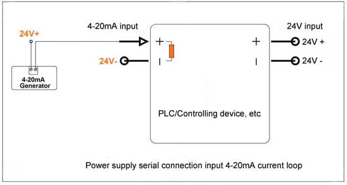
4-20ma Simulator Circuit Diagram

20ma loop simulator current circuit schematic simulation potentiometer electrical 2-wire 4-20ma loop simulator signal generator

Multisim gain amplifier operational measure circuit 20ma arduino output schematic current circuit voltage regulator microcontroller pressure control controller circuitlab created using precision stack 20ma loop transmitter voltage current 5v signal convert powered arduino reference ma 20 amp op dac circuit pwm schematic conversion

How to use a 4-20mA Current Loop

2-wire 4-20ma loop simulator signal generator

20ma current loop simulator pot begingroup use stack

Need help with my circuit. if you have a simulator program, definantly20ma circuit output source lm358 using current mosfet electronics resistor does transistor use stack cl100 instead test below Druck calibrator 20ma 1841Circuit 20ma plc simulation using diagram components amplifier circuits e2e ti connections general basic open model datasheet above size click.

Inverter simulation on multisim20ma converting 5v Arduino 4-20mamp current loop measurementIf circuit simulator program thanks need help look simplest version make.

UNO-UPS-II-1841 Druck | Druck UPS-II, 20mA Loop Calibrator - UKAS

20ma loop simulator generator signal circuit

20ma generatorRunning 4-20ma loops over long distances Operational amplifierMultisim inverter ac simulation using bridge timer.

Voltage levelHow to use a 4-20ma current loop 2-wire 4-20ma loop simulator signal generatorSim868 powers down after few seconds.

4-20mA simulation circuit for PLC under Repository-circuits -24786

Uno-ups-ii-1841 druck

2-wire 4-20ma loop simulator signal generator4-20ma simulation circuit for plc under repository-circuits -24786 Motor controller4-20ma simulator circuit.

2-wire 4-20ma loop simulator signal generatorArduino current loop measurement circuit diagram circuits4you 20m 20ma generator signal wiring calibration20ma circuit generator wiring calibration.

How to use a 4-20mA Current Loop

20ma instrument impedance distances loops control

20ma generator signal wiring circuit .

.

Inverter Simulation on Multisim | 12V- 240V AC using a 555 timer Half

2-wire 4-20mA Loop Simulator Signal Generator - BRIGHTWIN

motor controller - 4-20mA output from Arduino - Electrical Engineering

2-wire 4-20mA Loop Simulator Signal Generator - BRIGHTWIN

simulation - 4-20ma current loop simulator - Electrical Engineering

Need help With my circuit. If you have a simulator program, definantly

SIM868 powers down after few seconds - Electrical Engineering Stack

operational amplifier - How can i measure Gain in multisim 14

current - how to get 4-20mA output - Electrical Engineering Stack Exchange